

Key Takeaways
Replacing an MG sensor is usually straightforward once the failed component has been identified correctly. Diagnosis, careful installation, and a proper post-repair check matter as much as the replacement part itself.
- Identify the exact sensor before ordering a part.
- Check wiring, power, connectors, and related components first.
- Use the correct sensor, seal, bracket, and fasteners.
- Follow any required relearning or calibration procedure.
- Confirm the repair with live data and another scan.
Identify the MG sensor that needs replacement
An MG can use many different sensors, and their symptoms often overlap. A rough idle may involve an engine sensor, while a warning light could relate to emissions, braking, or body electronics. Start with the vehicle’s diagnostic information and the location of the suspected component rather than replacing the first part that appears in a search.
Common engine and emissions sensors
Engine and emissions sensors monitor conditions such as air flow, temperature, oxygen content, and throttle position. A faulty reading can affect starting, fuel delivery, idle quality, or emissions control, but the same symptoms may also come from a vacuum leak, poor ignition, or fuel problem. Check the engine code and sensor position carefully before beginning an MG sensor replacement.
Part identification is a small task that prevents a large amount of wasted work. The same care used when checking accurate item specifics online applies here: verify the model, engine, year, connector, and part number instead of relying on a broad description.
Camshaft and crankshaft position sensors
Camshaft and crankshaft position sensors tell the engine control system where rotating engine components are positioned. Failure can cause difficult starting, stalling, intermittent cutting out, or a crank-no-start condition. A stored code can point toward one of these sensors, but it does not prove that the sensor itself has failed.
Inspect the sensor’s mounting area and wiring for oil contamination, chafing, heat damage, or a loose connector. If the fault appears only when the engine is hot or the vehicle is moving, note those conditions because they can help reproduce the problem during testing. Guidance about camshaft sensor symptoms can provide useful background, but the vehicle’s own test results should guide the repair.
ABS, wheel speed, and body sensors
Wheel-speed sensors support anti-lock braking and stability functions, so a failure may bring on ABS, traction-control, or stability warning lights. Body sensors can serve other systems, including doors, air conditioning, lighting, or restraint-related functions. Their locations vary widely, from exposed wheel hubs to protected areas beneath trim.
Before removing one, determine whether the sensor is active, passive, magnetic, or part of a larger hub assembly. A damaged reluctor ring, wheel bearing, or corroded mounting surface can create a sensor-like fault. This is especially relevant when a warning returns immediately after a seemingly successful replacement.
Symptoms that help narrow down the fault
Symptoms are useful when they are recorded precisely. Note whether the issue occurs during cold starts, acceleration, braking, cornering, rain, or after the vehicle has warmed up. Also record which warning lamps appear and whether the engine loses power or simply enters a restricted operating mode.
The combination of symptoms is more informative than any single complaint. A no-start event points in a different direction from an isolated ABS light, while intermittent stalling deserves a close look at both position-sensor signals and their wiring.
Confirm the sensor is actually faulty
A diagnostic code is a starting point, not a verdict. The code may identify a circuit, signal range, or communication problem rather than a failed sensing element. Confirm the fault with visual checks, electrical tests, and live data before spending money on a part.

Reading diagnostic trouble codes
Connect a suitable scan tool and record every relevant code, including pending and history codes. Save freeze-frame information when available because it shows the conditions present when the fault was detected. Clear nothing until the evidence has been recorded.
A code describing a downstream oxygen-sensor circuit, for example, can involve wiring, a fuse, an exhaust leak, or an engine condition. Owner discussions about lambda sensor replacement may offer practical removal ideas, but a forum code should never replace testing on the actual car.
Testing wiring, connectors, and power supply
With the ignition off, inspect the harness from the sensor to its next connector or control module. Look for stretched wires, broken insulation, green corrosion, bent terminals, water entry, and connectors that do not lock securely. Then use the vehicle’s wiring information to check power, ground, reference voltage, and signal continuity.
Work carefully around airbag circuits and other safety systems. A continuity reading alone can be misleading if a wire fails only under vibration or load. Where appropriate, test while gently moving the harness, but do not force terminals or probe sealed connectors carelessly.
Comparing live data with expected readings
Live data can reveal a sensor that is stuck, implausibly slow, or reacting to the wrong engine condition. Compare readings during key-on, engine-off checks and then while starting, idling, or driving, depending on the sensor. Expected values vary by model and operating state, so use reliable service information rather than a generic internet number.
A good test explains the failure mechanism. If the signal changes normally but the code returns, investigate the circuit or a related mechanical problem. If the signal is absent with correct power and ground, the sensor becomes a much stronger suspect.
Avoiding misdiagnosis from related component failures
Sensors report what they detect; they do not correct the condition being detected. A misfire, damaged tone ring, intake leak, poor battery voltage, or timing problem can produce readings that look like sensor failure. Check the simplest related causes before committing to replacement.
A structured diagnostic process is easier to follow when each result determines the next step. The same principle appears in a carefully managed system: define the inputs, record the evidence, and avoid making a decision from one isolated observation.
Prepare for an MG sensor replacement
Preparation makes the repair safer and reduces the chance of fitting the wrong component. Confirm the vehicle details, review the replacement instructions, and inspect access before disconnecting anything. Some sensors take minutes to change; others require trim removal, a special socket, or work beneath the vehicle.
Choosing the correct replacement part
Match the replacement by vehicle identification number, model year, engine, transmission where relevant, and the original part number. Compare the connector, wire length, mounting points, sensing tip, and supplied seal. A part listed as compatible may still be wrong for a particular engine variant.
Do not assume that a similar-looking sensor will produce the same signal. If the original part includes a bracket, O-ring, clip, or heat shield, find out whether those items are included or must be transferred. Keep the old part until the new one has been checked and the repair is complete.
Gathering tools and safety equipment
Gather the tools before the vehicle is taken apart. A basic job may need only hand tools, while a sensor exposed to heat or corrosion may require penetrating fluid, a torque wrench, a scan tool, and a purpose-made socket. Use eye protection and gloves, and support the vehicle with proper stands whenever access underneath is necessary.
A sensible preparation list usually includes:
- The correct replacement sensor and any required seal.
- A scan tool capable of reading and clearing relevant codes.
- Basic sockets, extensions, pliers, and a torque wrench.
- Electrical contact cleaner and a small inspection light.
Having these items ready prevents rushed improvisation. It also makes it easier to stop when a connector or fastener needs a different approach rather than damaging it through force.
Locating the sensor and checking access
Use a repair manual or reliable diagram to find the sensor and trace its wiring. Check whether the component is reached from above, below, through a wheel arch, or after removing a cover. Photograph the area before removal so the routing and clips can be restored correctly.
Look for nearby hot surfaces, moving belts, sharp edges, and fluid lines. If the sensor is mounted in an exhaust or hub area, allow enough time for the components to cool and expect corrosion around the fasteners.
Disconnecting the battery and protecting vehicle systems
Follow the vehicle-specific instructions before disconnecting the battery. Some systems may require a window, radio, steering, or security reset after power is removed, while others should remain powered during certain diagnostic procedures. Never disconnect a battery while the ignition is on or while a control module is being programmed.
If battery disconnection is not appropriate for the procedure, switch off all electrical loads and follow the service information. Keep the key away from the vehicle so it cannot be activated accidentally, and protect exposed connectors from dirt and moisture.
Remove the faulty sensor
Removal should be deliberate, especially when the sensor sits in a hot, dirty, or corrosion-prone area. Clean first, release the connector second, and remove the retaining hardware only after the sensor can be withdrawn safely. Avoid twisting a sensor against its wiring or levering against fragile housings.
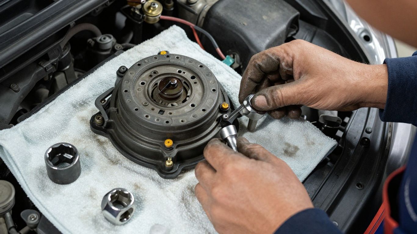
Cleaning the surrounding area
Brush loose dirt away from the sensor base and connector before opening the circuit. Use an appropriate cleaner where oil or road salt has collected, taking care not to push debris into an open port. A clean work area helps prevent contamination from entering the engine, hub, or exhaust system.
Good maintenance habits matter beyond this repair. A simple propeller maintenance routine demonstrates the same useful pattern: inspect for damage, clean carefully, and replace a component when wear makes continued use unsafe. The specific parts differ, but the discipline is similar.
Releasing connectors without causing damage
Find the locking tab and release it in the direction intended by the connector design. Pull on the connector body, never on the wires, and use a small pick only when the locking mechanism is clearly accessible. If the plug is stuck, clean around it and work patiently rather than bending the terminals.
Examine both halves after separation. A pushed-back terminal, moisture mark, or overheated plastic may be the real cause of the fault. Repair the connector or harness before fitting a new sensor if the electrical connection cannot be trusted.
Removing seized fasteners and old seals
Apply penetrating fluid to corroded fasteners and allow it time to work. Use the correct-size tool with steady pressure, supporting the sensor housing where necessary. If an exhaust sensor is seized, a specialist removal socket may be safer than an ordinary open-ended wrench.
Once the sensor is out, remove the old O-ring, crush washer, or gasket completely. Do not reuse a seal that has flattened, torn, or hardened. Clean the mating surface without scratching it, since a damaged surface can cause leaks or allow movement.
Handling sensors in tight or difficult locations
Restricted access increases the risk of dropping hardware or damaging nearby components. Lay out extensions and adapters before starting, and protect delicate wiring while tools are being positioned. If a sensor cannot be removed without excessive force, stop and reassess the access route.
Some jobs are better handled by a repair professional, particularly when the sensor is near fuel, high-voltage, restraint, or pressurized systems. A short pause is cheaper than a broken fastener, damaged harness, or component that must be removed to recover a fragment.
Install and configure the new sensor
Installation is more than inserting the replacement and tightening a bolt. The new part must sit in the correct position, seal properly, and connect without strain on its wiring. Keep the old and new components together until every detail has been compared.
Comparing the old and new parts
Check the connector shape, sensor tip, mounting hole, wire length, and orientation against the removed part. Confirm that protective caps are removed only immediately before installation. If the parts differ, stop and verify the application instead of forcing the connector or modifying the bracket.
Small differences can affect clearance from a reluctor, tone ring, belt, or exhaust surface. Record any supplied instructions, especially those covering an air gap, alignment mark, or required orientation.
Fitting seals, brackets, and retaining bolts
Install a new seal when one is specified, and use only the lubricant or sealant recommended for that application. Seat the sensor squarely and ensure the bracket is not twisted. Tighten retaining bolts to the specified torque; overtightening can crack a plastic body or distort a sensor mounting point.
Keep wiring away from hot and moving parts, using the original clips and guides. A correctly torqued fastener and properly routed harness are part of the repair, not finishing touches to be dealt with later.
Connecting the wiring correctly
Push the connector together until its lock engages, then give the body a gentle pull to confirm it is secured. Route the harness as it was originally installed, with enough slack for movement but no loose loop near a belt, tire, or exhaust. Reconnect any grounds, brackets, or protective covers removed during access.
Before restoring power, inspect the area for forgotten tools, loose clips, pinched wires, and fluid leaks. This simple check catches many installation errors while they are still easy to correct.
Completing relearning or calibration procedures
Some vehicles require a sensor relearn, throttle adaptation, steering-angle calibration, or other configuration step after a component is replaced. The required procedure depends on the sensor and vehicle system. Follow service information and use a scan tool with the necessary function rather than assuming a drive will complete every adaptation.
Calibration should be carried out only after the mechanical installation and wiring have been checked. If the procedure will not complete, treat that as diagnostic evidence and investigate the underlying code instead of repeatedly attempting the same command.
Test the vehicle after replacement
A replacement is not confirmed until the vehicle behaves normally and the original fault does not return. Begin with stationary checks, then move to a controlled drive if the vehicle is safe to operate. Keep the scan tool connected when practical so changes in the sensor signal can be observed.
Clearing stored fault codes
Clear codes only after recording them and completing the repair. Some modules may need to be scanned separately, and clearing codes does not repair an active fault. If a code returns immediately with the engine off, recheck the connector, power supply, and circuit before driving.
After clearing, switch the ignition off and back on as instructed by the scan tool or service information. This gives the modules a clean opportunity to initialize and may reveal a connection problem early.
Checking live readings and warning lights
Watch the relevant live data during key-on, starting, idle, and any applicable system self-test. The reading should be plausible and respond to the condition being changed. Confirm that warning lights extinguish as expected, while remembering that some monitors need a completed drive cycle before they show ready status.
Do not judge success by a quiet dashboard alone. A stored pending code or implausible live value can indicate that the original problem remains even if the main warning lamp has not returned.
Performing a controlled road test
Choose a familiar route with safe places to stop. Reproduce the operating conditions associated with the original complaint, but avoid aggressive driving until braking, steering, engine response, and warning lights have all been checked. Pay attention to starting, idle quality, acceleration, gear changes, and any return of the original symptom.
A road test should be long enough for the relevant system to operate through more than one condition. If the fault was temperature-related or intermittent, a very short trip may not provide meaningful confirmation.
Confirming the repair with a second diagnostic scan
Scan the vehicle again after the road test and compare the results with the initial record. Check current, pending, and history codes, along with readiness information and the sensor’s live reading. A clean second scan is stronger evidence than simply seeing the warning light go out.
If the same code returns, do not keep replacing parts. Revisit the wiring, mechanical timing, air or exhaust leaks, wheel components, and module inputs that could create the same diagnostic pattern.
MG sensor replacement cost and repair decisions
The price of an MG sensor replacement depends on the part, access, corrosion, diagnosis, and any calibration required afterward. A low-cost sensor can still become an expensive repair if the connector is damaged or a seized fastener breaks. Compare the complete job rather than the part price alone.
Parts, labor, and diagnostic costs
A repair estimate may include an initial scan, testing time, the sensor, seals or hardware, labor, and a final diagnostic check. Ask whether calibration, a road test, and follow-up scanning are included. The cheapest estimate is not always the lowest total cost if it omits the diagnosis that prevents a repeat failure.
For household budgeting, a planned home-buying budget is a useful general reminder: account for the less visible costs as well as the headline figure. Apply the same thinking to vehicle repairs by allowing for access time, corrosion, and related parts.
OEM, aftermarket, and used sensor options
An original-equipment sensor may offer the closest match to the factory specification, while a reputable aftermarket part can be suitable when its application and quality are clear. A used sensor may cost less, but its remaining service life and history are uncertain. Confirm warranty terms and return conditions before buying.
Do not select a part solely because its connector looks right. Verify the exact application, electrical characteristics, and any required seal or bracket. Paying for the wrong part twice is rarely economical.
When professional installation is worthwhile
Professional help is sensible when diagnosis requires specialist equipment, access involves lifting the vehicle, or the sensor is part of a safety-critical system. It is also worthwhile when the fault is intermittent, the wiring is damaged, or the component is seized in a delicate housing.
A technician can test the system before and after replacement and may have the equipment needed for coding or calibration. Share your recorded symptoms and scan results; clear information can reduce diagnostic time.
Preventing repeat sensor failures
A new sensor may fail again if the cause of the original problem remains. Protect the harness from heat and abrasion, repair oil or water leaks, and make sure mounting surfaces and connectors are clean. During routine servicing, inspect exposed sensors and wiring rather than waiting for a warning light.
Risk-based planning is helpful here, much as it is when assessing environmental investment risks: identify the conditions that can cause failure, address them early, and keep records of what was changed. That approach will not prevent every fault, but it reduces avoidable repeat work.
Conclusion
A successful MG sensor replacement begins with accurate diagnosis and ends with a verified repair. Check the circuit and related components, fit the correct part carefully, complete any required calibration, and use a second scan to confirm that the original fault has truly been resolved.
Frequently Asked Questions
How do I know which MG sensor needs replacing?
Use the stored diagnostic codes as a starting point, then confirm the suspected sensor through wiring checks, power and ground tests, visual inspection, and live-data comparison. Symptoms alone are rarely specific enough.
Can a bad connector cause a sensor fault code?
Yes. Corrosion, loose terminals, broken wires, water entry, or a poor ground can interrupt the sensor signal and create a code that appears to identify the sensor. Inspect and test the circuit before replacing the component.
Should I disconnect the battery before replacing a sensor?
Follow the vehicle-specific repair instructions. Battery disconnection may protect some systems, but it can also erase settings or require resets. Never disconnect it while the ignition is on or during module programming.
Do all replacement sensors need calibration?
No. Some sensors work after installation and code clearing, while others require relearning, adaptation, or calibration. The required procedure depends on the sensor and vehicle system.
Is an aftermarket sensor safe to use?
A reputable aftermarket sensor can be suitable when it is listed for the exact vehicle and has appropriate quality and warranty support. Confirm the connector, specification, fit, and supplied hardware before installation.
Why has the warning light returned after replacement?
The original fault may still be present, or a related issue such as damaged wiring, a mechanical timing problem, a leak, or a failed reluctor may be producing the same code. Perform another scan and continue testing rather than replacing another part immediately.
When should a professional replace the sensor?
Seek professional help when the sensor is difficult to access, seized, connected to a safety-critical system, or requires specialist calibration. Professional diagnosis is also worthwhile when the fault is intermittent or the wiring has been damaged.